
|
LaspecMX Software | |
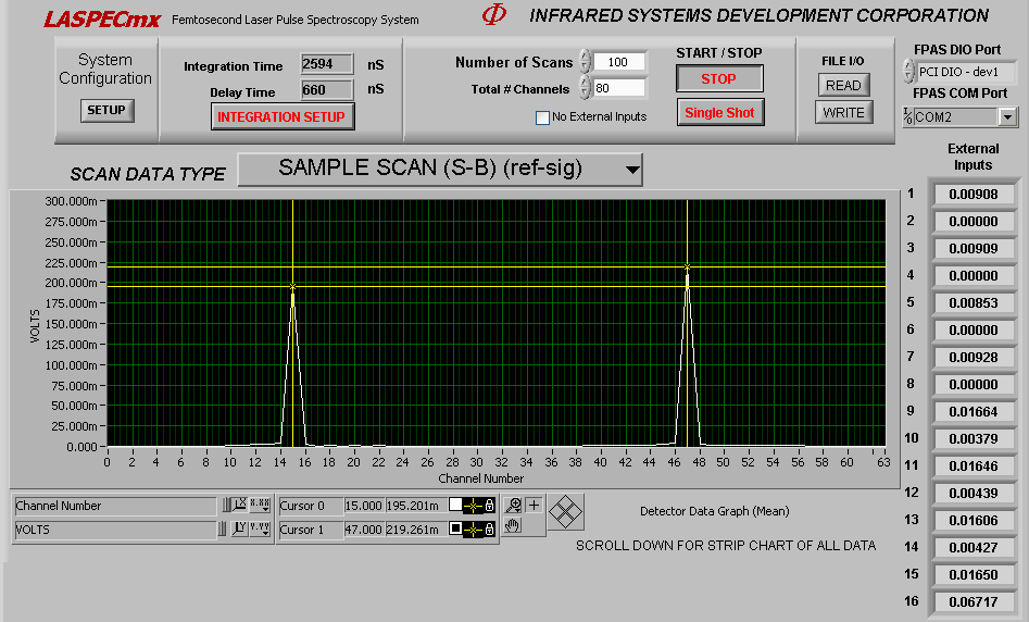
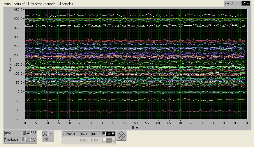
The LASPECmx (Laze – spec) Software was developed specifically for the FPAS-3216, FPAS-6416, and FPAS-0144 systems. The software is written in Labview 2012 and all of the source files, with exe and installer are provided. The main screen presents the data gathered from the detector array, with the external input values listed to the right of the main graph. All of the values presented are scaled to 5 Volt levels. The software allows the user to change the integration parameters, such as Integration Gate Delay Time, and Integration Gate Width Time. Having the integration gate just slightly wider than the signal pulse will provide the best signal to noise. The Scan Mode selector above the main graph selects the type of scan acquired: Background, Reference, Sample, Sample/Reference, Chopped and Zero External Inputs. The background is the residual level of the inputs without any laser power applied to the detector. Reference is the full laser power applied without any sample (100% scan). And the sample scan is the difference between background and sample, and the Sample/Reference is the sample data divided by the reference data, where a value of 1 indicates maximum. Zero External Channels allows the residual DC level to be subtracted from the External inputs. Chopped Mode is for using a chopper in the optical path to alternately acquire reference and signal data points. External Input #16 is used for connecting the output of the chopper sync signal to the system. The software will monitor the level at External Input #16 and use this information to determine the phase of the data acquisition. |

| Laser Pulse Repetition Rate: | 0 to 125Khz. |
| Integration Time: | Adjustable in steps between 50 to 5100 ns. |
| Integration Delay: | Adjustable in steps between 50 to 1200 ns. |
| Integrator Type: | Boxcar type, Low noise, current steering, auto-reset, integrator section. |
| Photoconductive: | HgCdTe (MCT)-Low Noise 10 Mhz Amplifier with Bias. |
| Photovoltaic: | InSb – Low Noise FET 5 Mhz Amplifier with Zero Volt Bias |
| HgCdTe (PVMCT) – Low Noise 10 Mhz Amplifier with Zero Volt Bias | |
| A/D Conversion: | 16 Bit, +5V to –5V input Multiplexed 16 channels / AD converter |
| Maximum Number of samples: | 1 Million complete scans of all channels |
| FIFO Memory: | 1024 x 16 FIFO Memory |
| Data Communications: | FIFO Memory is read out by a 20 Mhz digital communications port. |
| Signal: | Approx. 7 Volts from 80 femtosecond laser at 7 um |
| EQV Noise: | Less than 1.5 nv/Hz1/2 at Input. |
| System Signal to Noise: | >>100 db (100,000:1) at 1000 scans p-p |
| Digital Noise: | +/- ½ LSB |
| Typical System Noise: | +/- 2 LSB rms (1000 Scans @ 2Khz Laser Rep Rate) |
| Digital Dynamic Range: | -32767 to + 32767 = 65535 (16Bits) |
| Analog Dynamic Range: | -5 V to +5 V |